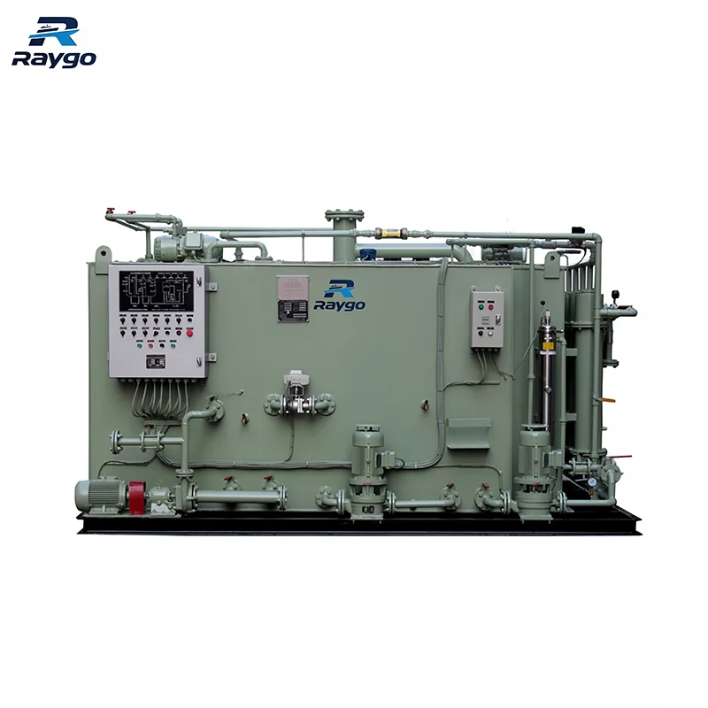
Marine heat exchangers are used throughout a vessel to transfer thermal energy between fluids without allowing the fluids to mix during normal operation. They support engine cooling, lubricating-oil temperature control, fuel heating, steam condensation, freshwater production, HVAC systems and other auxiliary services.
Their function is broader than simply removing unwanted heat. A correctly selected exchanger must deliver the required heat duty while keeping pressure drop, corrosion, fouling, vibration and maintenance requirements within acceptable limits. A unit that performs well under clean test conditions may still underperform at sea if cooling-water temperature, biological activity, sediment, pump head, control behavior or cleaning access were not considered during selection.
This guide explains the working principles of marine heat exchangers, the differences between common constructions, the parameters required for selection, typical failure modes, and the practical checks needed before cleaning, repairing or replacing a unit.
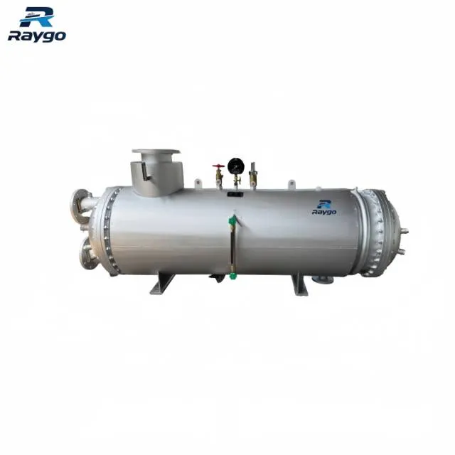
What a Marine Heat Exchanger Does
A marine heat exchanger transfers heat from a higher-temperature fluid to a lower-temperature fluid through a separating wall. The separating surface may be a tube wall, a corrugated plate or another pressure-retaining barrier. The two media normally remain in separate flow passages.
The outlet temperatures do not normally become equal. Heat transfer slows as the temperature difference becomes smaller, so practical equipment must retain a finite temperature approach. Final temperatures depend on flow rate, heat capacity, heat-transfer area, overall heat-transfer coefficient and flow arrangement.
Q = ṁ × cₚ × (Tᵢₙ − Tₒᵤₜ)
For a single-phase stream, Q is the heat duty, ṁ is the mass flow rate, cₚ is the specific heat capacity, and T is the fluid temperature.
Q = U × A × F × ΔTₗₘ
For exchanger sizing, U is the overall heat-transfer coefficient, A is the effective heat-transfer area, F is a correction factor and ΔTₗₘ is the log mean temperature difference. These relationships explain why reduced flow, trapped air, deposits or an incorrect valve position can reduce duty even when no mechanical failure is visible.
Flow Arrangements and Performance
The principal flow arrangements are counter-current, co-current and cross-flow. Counter-current flow often makes better use of the available temperature difference and may permit a closer outlet-temperature approach. Co-current flow sends both media in the same direction, while cross-flow is common where one stream passes across a tube bank or finned surface.
Flow arrangement cannot be selected on temperature performance alone. Nozzle position, available space, venting, draining, allowable pressure drop, phase change and maintenance access also influence the final design.
Direct Seawater Cooling and Central Cooling Systems
Some vessels use seawater directly in local equipment coolers. Many modern vessels use a central cooling system in which a closed freshwater circuit cools engines and auxiliary equipment, while one or more central coolers reject heat from the freshwater loop to seawater.
Central cooling can reduce the number of components directly exposed to seawater and simplify corrosion and fouling management. Direct seawater cooling may use fewer circuits, but every seawater-wetted exchanger must tolerate chloride exposure, marine growth, suspended solids and possible erosion. The preferred arrangement depends on vessel design, redundancy philosophy and operating profile.
- Direct seawater cooling: equipment fluid → local seawater cooler → overboard discharge.
- Central freshwater cooling: equipment fluid → freshwater cooler → central cooler → seawater.
- High-temperature and low-temperature freshwater circuits: separate temperature levels serve jacket water, charge air, lubricating oil and auxiliary consumers.
Marine Heat Exchanger Types Available from Raygo
Raygo Marine can provide shell-and-tube heat exchangers, gasketed plate heat exchangers, brazed plate heat exchangers and fully welded plate heat exchangers. Because model systems vary by supplier and project, this technical article does not publish a universal model list. Final model selection is based on duty, fluids, pressure, temperature, allowable pressure drop, materials and installation constraints.
A common heat-transfer area range is 0.5–500 m². Larger custom ranges can be engineered when the application requires them. The relationship between area and model is project-specific and should be established through thermal and hydraulic calculations rather than a fixed public table.
1. Shell and Tube Heat Exchanger
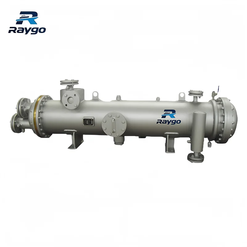
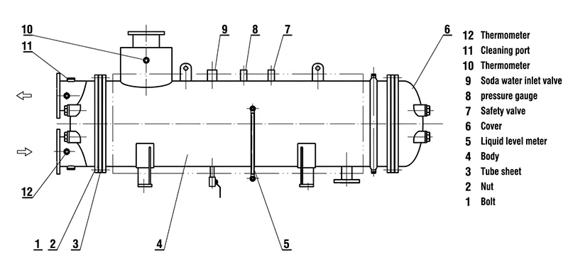
A shell-and-tube exchanger normally contains a shell, tube bundle, tube sheets, channel covers or water boxes, nozzles, supports and, where required, baffles. One medium flows through the tubes and the other flows through the shell around the tube bundle. Baffles support the tubes and guide shell-side flow.
Straight-tube designs may allow mechanical cleaning from the ends when both tube sheets are accessible. U-tube and floating-head arrangements can accommodate differential thermal expansion, but each construction has different inspection and cleaning limitations. Tube diameter, wall thickness and number of passes are determined for the selected model and duty.
2. Gasketed Plate Heat Exchangers
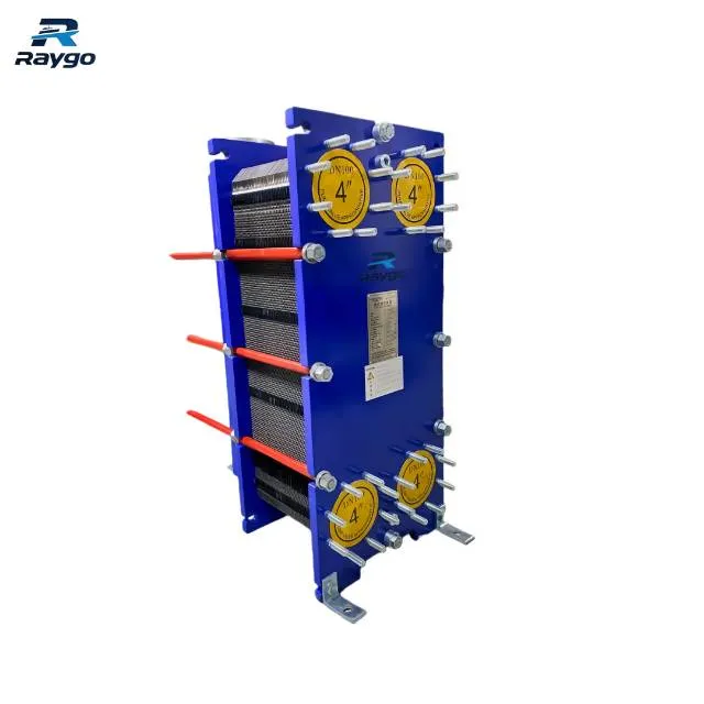
A gasketed plate heat exchanger uses a compressed pack of corrugated plates. Gaskets direct the hot and cold media into alternating channels and seal the plate pack. The corrugations increase stiffness and promote turbulence, which can improve heat transfer while also creating hydraulic resistance.
Under the same or comparable clean-fluid operating conditions, corrugated plate passages can provide heat-transfer coefficients approximately three to five times those of conventional tubular arrangements. The actual result depends on fluid properties, velocity, plate pattern, temperature approach, fouling allowance and allowable pressure drop, so the ratio should not be treated as a universal performance guarantee.
Plate heat exchangers are structurally compact, relatively light and require less installation space in many liquid-to-liquid duties. The number and pattern of plates, channel spacing, port size and pass arrangement must be selected together. Adding plates may increase area, but it also changes channel velocity and pressure drop and is not a universal correction for every performance problem.
3. Brazed and Fully Welded Plate Heat Exchangers
Brazed plate units use a permanently bonded plate pack and are commonly selected where a compact, sealed construction is suitable for the fluid, pressure and temperature. Fully welded plate exchangers extend the plate concept to duties where elastomer gaskets are unsuitable or leakage tolerance is low. Their maintainability, inspection method and repair strategy differ from those of gasketed plate units and must be considered during selection.
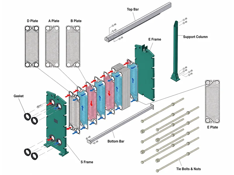
Plate vs. Shell-and-Tube: A Conditional Comparison
| Selection Factor | Gasketed Plate | Shell-and-Tube |
| Footprint | Usually compact and light for suitable clean liquid-to-liquid duties. | Usually larger, but geometry and nozzle arrangement may suit some engine-room layouts. |
| Pressure and temperature | Limited by plate, frame, gasket and connection design; welded types extend the range. | Often selected for higher-pressure or higher-temperature duties, subject to construction and code. |
| Dirty or particulate fluids | Narrow channels may block if screening or velocity is inadequate. | Larger passages and accessible tubes may be more tolerant, depending on design. |
| Temperature approach | Can achieve a close approach in suitable clean-fluid service. | Can also be designed efficiently, but may require more area for the same approach. |
| Maintenance | Plate pack can be opened; correct plate order, gasket condition and tightening dimension are essential. | End covers may allow tube cleaning; bundle removal depends on construction and available space. |
| Capacity adjustment | Area may sometimes be changed by adding or removing plates within frame limits. | Capacity change normally requires tube-bundle or exchanger modification. |
| Leak behavior | External leakage may be visible; plate failure can cause cross-contamination. | Tube or tube-sheet leakage can cause cross-contamination; individual tubes may sometimes be plugged. |
Neither design is automatically better. The correct choice is the design that meets the thermal duty, hydraulic limits, material requirements, inspection needs and vessel constraints with an acceptable lifecycle risk.
Applications of Marine Heat Exchanger in Marine Systems:
Jacket-water cooling: Removes heat from engine high-temperature or low-temperature freshwater circuits. Selection must consider engine load, control temperature and seasonal seawater variation.
Lubricating- and hydraulic-oil cooling: Controls oil viscosity and protects bearings, gears and hydraulic equipment. Oil-side fouling and excessive oil temperature can affect performance and service life.
Fuel-oil heating: Uses steam, hot water or thermal oil to reach the viscosity required by fuel-treatment or injection equipment. The target temperature is determined by fuel properties, viscosity requirements and the equipment manufacturer’s instructions; no universal target range should be applied.
Charge-air cooling: Transfers heat from compressed intake air to cooling water. Air-side fouling, condensate drainage and pressure loss are important.
Steam condensation and drain cooling: Condenses steam or cools hot drains while recovering condensate where the system arrangement permits.
Freshwater production: Evaporator and condenser sections transfer heat during desalination or low-temperature evaporation.
HVAC and chilled-water systems: Transfers heat between chilled water, condenser water and utility circuits.
Waste-heat recovery: Recovers energy from jacket water, exhaust-related systems, condensate or other warm streams when a useful heat sink is available.
Technical Data Required for Selection
| Data Group | Required Information |
| Thermal duty | Required heat load; minimum, normal and maximum load; inlet and target outlet temperatures. |
| Flow data | Mass or volume flow rate, density, specific heat, viscosity and phase condition for both sides. |
| Pressure data | Normal pressure, design pressure, test pressure, pressure differential and transient conditions. |
| Pressure-drop limit | Maximum allowable pressure loss on each side, including a suitable fouling margin. |
| Fluid composition | Freshwater, seawater, glycol, oil, fuel, steam, condensate or process fluid, including concentration and contaminants. |
| Fouling tendency | Marine growth, silt, hardness, sludge, corrosion products and expected cleaning frequency. |
| Material requirements | Plate or tube material, shell or frame material, gasket or seal material, coating, corrosion allowance and galvanic compatibility. |
| Installation | Footprint, height, weight, nozzle orientation, supports, lifting path and maintenance clearance. |
| Control philosophy | Bypass, three-way valve, cooling-water regulation, variable-speed pumping, temperature control and redundancy requirements. |
| Compliance | Vessel class, flag, pressure-code basis, inspection scope, certificates and documentation. |
Design pressure, operating pressure, test pressure, allowable differential pressure and detailed dimensions vary among models. These values are therefore defined in the selected model datasheet, approved drawing or project technical agreement rather than as one universal public value.
Thermal Sizing and Pressure-Drop Trade-Off
Increasing velocity generally improves convective heat transfer and can reduce deposit formation, but it also increases pressure drop and may increase erosion risk. Lower velocity reduces pumping demand but may encourage sedimentation, marine growth or poor flow distribution. Selection is therefore a balance rather than a search for the highest possible heat-transfer coefficient.
Allowable pressure drop has a design range rather than one fixed universal value. It is established from exchanger type, fluid properties, flow rate, available pump head, control requirements and fouling allowance. For replacement equipment, the original nameplate area alone is not enough to prove equivalence; duty, flow, pressure drop, material, connection size and system behavior must all be checked.
Material Selection and Seawater Corrosion
Seawater service combines chlorides, dissolved oxygen, biological activity, suspended solids and possible high local velocity. Material selection must therefore consider more than general corrosion resistance. Copper-nickel alloys, titanium, stainless steels and aluminum bronze can all be used in marine systems, but the exact grade and its water-quality, temperature and velocity limits must be selected for the actual project rather than published as a universal rule.
Shells and channel covers are commonly manufactured from carbon steel or stainless steel. Other components, including frames, flanges, fasteners and wetted parts, are selected by model and service condition. For shell-and-tube exchangers, the inside of the channel cover may use epoxy resin, protective paint or rubber lining. A stainless-steel cover normally does not require an internal coating.
Sacrificial anodes are commonly made of zinc and installed in the channel cover or water box. Replacement criteria vary by design and operating condition; as a practical reference, replacement is often considered when less than approximately 50% of the original anode remains. The final criterion should follow the equipment manual and inspection plan.
Gasket and Seal Selection
For gasketed plate heat exchangers, elastomer selection depends on fluid composition, concentration, temperature, pressure, cleaning chemical, expected service life and thermal cycling. The following values are Raygo’s current general reference ranges. Final limits must be confirmed for the actual compound, plate-and-gasket system and selected model.
| Gasket Family | Typical Media | Continuous Temperature | Short-Term Temperature | Pressure Reference |
| NBR | Oil and oil-based media | −15 to 120°C | 130°C | Generally ≤16 MPa; special structures may reach 40 MPa |
| EPDM | Water and steam | −25 to 150°C | 160°C | Generally ≤16 MPa; special structures may reach 40 MPa |
| FKM | Oil and chemical media | −55 to 230°C | 230°C | Generally ≤16 MPa; special structures may reach 40 MPa |
Clip-on gaskets are now commonly used, but the attachment method is model-specific and should not be described as universal for every plate heat exchanger.
Installation and Commissioning
Shell-and-tube heat exchangers are most commonly installed horizontally, while plate heat exchangers are most commonly installed vertically. Final orientation, venting, draining, flow direction and nozzle arrangement must follow the approved drawing and the selected model instructions.
- Confirm that foundations and supports can carry operating, flooded and maintenance loads under vessel motion.
- Provide sufficient clearance to open the plate pack, remove channel covers or withdraw the tube bundle.
- Install vents at high points and drains at low points so air and liquid can be removed safely.
- Use strainers where particles could block channels or tubes. Filter rating is selected according to exchanger type, fluid, particle characteristics and manufacturer requirements; there is no single universal value.
- Avoid excessive piping loads at nozzles and confirm alignment before connection.
- Flush new piping before commissioning to prevent welding debris, scale and gasket fragments from entering the exchanger.
- Fill and warm the unit gradually where thermal shock is a concern.
- Verify plate-pack tightening dimension, plate order or tube-side cover assembly according to the manufacturer’s instructions.
Control Philosophy and Supply Boundary
Outlet temperature may be controlled by a three-way bypass valve, a cooling-medium regulating valve, a variable-speed pump or another approved system arrangement. The control method must maintain adequate flow through the exchanger and avoid unstable operation.
Three-way valves, bypass assemblies, temperature controllers, PLCs, VFDs and associated instruments are not part of Raygo’s current standard heat-exchanger supply scope. They may still be discussed as system-level control options, but the customer should define the required control philosophy and interfaces during the project review.
Common Failure Modes and Troubleshooting
| Symptom | Possible Causes | Technical Checks |
| Cooled-fluid outlet temperature rises | Low cooling flow, warm seawater, fouling, trapped air, bypass leakage, wrong valve position or changed process duty. | Compare current and baseline temperatures, flow and pressure drop; verify valves, pumps and venting. |
| Pressure drop increases | Blocked channels or tubes, marine growth, silt, scale, collapsed gasket or incorrect plate assembly. | Check strainers and differential pressure; inspect and clean using a material-compatible method. |
| Pressure drop decreases while duty worsens | Bypass flow, poor internal distribution, missing or incorrectly assembled plates, tube leakage or reduced flow. | Confirm flow path, valve position, plate sequence and possible internal damage. |
| External leakage | Loose plate pack, aged gasket, damaged sealing surface, cover-gasket failure, corrosion or nozzle stress. | Depressurize and inspect; do not compensate indefinitely by over-tightening. |
| Cross-contamination | Cracked plate, perforated tube, tube-sheet leak or gasket failure between circuits. | Isolate promptly and use pressure testing, sampling or approved leak-detection methods. |
| Vibration or noise | Two-phase flow, flashing, water hammer, pump cavitation, unstable control, unsupported piping or flow-induced vibration. | Check temperatures, pressures, venting, supports, valves and pump suction conditions. |
| Repeated rapid fouling | Unsuitable velocity, poor straining, contaminated fluid, high scaling tendency or incorrect cleaning practice. | Investigate root cause and operating conditions rather than relying on repeated cleaning alone. |
Cleaning, CIP and Gasket Replacement
Marine fouling may include biological growth, shells, silt, corrosion products, mineral scale, oil sludge and degraded additives. The cleaning method must match the deposit and the exchanger materials. CIP chemical, concentration, temperature and circulation time vary by exchanger type, plate or tube material, gasket compound and deposit. Cleaning should therefore follow the equipment manufacturer’s manual rather than a universal chemical recipe.
For gasketed plate heat exchangers, use clean-in-place circulation only with chemicals approved for the plate and gasket materials. Record the tightening dimension and plate sequence before opening the frame, and inspect plates for pitting, cracks, deformation and gasket-groove damage.
A typical clip-on gasket replacement sequence is:
- Remove the old gasket.
- Clean the sealing groove and keep it dry, oil-free and free of debris.
- Install the new gasket in the original orientation and make sure it is fully seated without lifting.
- Engage the clips in the corresponding slots.
- Reassemble the plate pack and complete the required leakage or pressure checks.
For shell-and-tube heat exchangers, open covers only after isolation, draining, cooling and confirmation that no pressure remains. Mechanical brushing, controlled water jetting or approved chemical cleaning should be selected according to tube material and deposit type. Inspect tube ends, tube sheets, water boxes, baffles and sacrificial anodes where fitted.
Operating Limitations
Plate heat exchanger limitations include sensitivity of narrow channels to debris, gasket compatibility limits, leakage caused by incorrect tightening or plate order, and the need to review large pressure differentials or pressure pulsation.
Shell-and-tube limitations include larger footprint and mass, possible dead zones or bypassing, space required for bundle removal, and the difficulty of detecting tube-side or shell-side fouling without trend data or inspection.
Seawater limitations include accelerated fouling in warm or biologically active water, chloride and galvanic-corrosion risks, and erosion-corrosion at excessive local velocity. Retrofit projects must also verify pumps, valves, foundations, connections, controls and maintenance access; matching flange sizes and footprint alone does not prove thermal or hydraulic equivalence.
Vessel Motion, Classification and Testing
Marine heat exchangers may need to be designed or tested for specified vibration, inclination, rolling and pitching conditions. The applicable requirements are normally defined by the vessel’s classification society and project specification.
The actual inspection and test scope varies by exchanger model, function, pressure and contract. Hydrostatic testing, pneumatic or leak testing, performance testing, dye penetrant examination, radiography, ultrasonic examination and other inspections should be specified in the project quality plan rather than presented as one universal package for every model.
| Abbreviation | Classification Society | Country |
| CCS | China Classification Society | China |
| ABS | American Bureau of Shipping | United States |
| LR | Lloyd’s Register | United Kingdom |
| DNV | DNV | Norway |
| BV | Bureau Veritas | France |
| NK | ClassNK / Nippon Kaiji Kyokai | Japan |
| RINA | RINA | Italy |
Each classification society applies its own rules and approval procedures. The society list above identifies the organizations only and should not be interpreted as a claim that every Raygo model holds a current type-approval certificate. Applicable certificates, inspections and submission requirements are determined for each project.
Documentation, Spare Parts and Project Support
Depending on the project and contract scope, Raygo can provide general arrangement drawings, P&ID information, thermal calculations, pressure-drop calculations, material certificates, test reports, operating instructions and spare-parts lists.
Common spare parts include gaskets, plates, sealing rings, sacrificial anodes and tube plugs. A recommended two-year spare-parts package is prepared according to exchanger type, model, operating conditions and contract requirements.
Project cases, product images, structural illustrations and certificate images can be used for public communication where the material is relevant and approved for release. Captions should accurately match the product type and should not add unsupported model, material, pressure or certification claims.
Replacement and Retrofit Assessment
When replacing an existing marine cooler or heater, collect the original datasheet, nameplate, drawings, operating logs and failure history. If the unit is underperforming, the replacement should not simply reproduce the original dimensions without identifying the cause.
- Confirm actual operating duty rather than relying only on the original design duty.
- Check whether vessel load, fuel type, cooling-water temperature or flow has changed.
- Verify available pump head and current piping pressure losses.
- Review repeated fouling, corrosion, leakage or vibration mechanisms.
- Confirm foundation, centerline, nozzle orientation and maintenance envelope.
- Assess control-valve sizing and bypass arrangement.
- Confirm class, flag and shipyard approval requirements.
- Plan isolation, lifting, pipe modification and commissioning work.
Technical FAQ
How is the required heat-transfer area determined?
Area is calculated from heat duty, overall heat-transfer coefficient and effective temperature difference. The calculation must also verify pressure drop, fouling allowance, fluid properties and design margins. Raygo’s common area range is 0.5–500 m², with larger custom ranges available where required.
Is a plate heat exchanger always more efficient than a shell-and-tube unit?
No. Plate units can provide high heat-transfer coefficients and compact size in suitable clean-fluid service, while shell-and-tube units may be preferred for higher pressure, higher temperature, fouling tolerance or mechanical cleaning. The correct selection depends on the full duty and lifecycle requirements.
Which fluid should be placed on the tube side or plate channel?
The decision depends on pressure, corrosion, fouling, viscosity, allowable pressure drop, cleaning method and leakage consequence. There is no universal rule for every vessel.
How often should a marine heat exchanger be cleaned?
Cleaning frequency should follow operating trends, water quality, fouling rate, pressure drop and planned-maintenance requirements. A fixed interval can support planning, but condition-based evidence provides a stronger basis.
Can more plates always be added to improve capacity?
Only within the frame and hydraulic limits. Adding plates changes channel count, velocity and pressure drop, so the revised arrangement must be recalculated.
What information is needed for a replacement quotation?
Provide fluid data for both sides, flow rates, inlet and required outlet temperatures, normal and design pressures, allowable pressure drops, material requirements, installation drawings, connection details, control philosophy, class requirements and the original datasheet where available.
Conclusion
Marine heat exchanger performance depends on the complete system, not only the nominal heat-transfer area. Reliable operation requires correct duty definition, hydraulic checking, material compatibility, suitable control, accessible maintenance and trend-based monitoring. Plate and shell-and-tube exchangers can both perform effectively when their construction matches the actual fluids, pressures, fouling conditions and vessel constraints.
Raygo Marine can provide selection recommendations, thermal calculations, structural design, classification-submission support and equipment supply support. For a vessel-specific technical review, provide the fluid properties, flow rates, inlet and required outlet temperatures, normal and design pressures, allowable pressure drops, installation drawings, material requirements and classification scope. These data allow the applicable exchanger configuration and project documentation package to be defined accurately before final selection.