Marine heat exchanger selection should not be based only on price, equipment size, or a simple product category. A suitable exchanger must match the engine cooling duty, fluid conditions, seawater quality, allowable pressure drop, material requirements, installation space and maintenance method.
For shipowners, marine engineers, shipyards, fleet operators and marine equipment distributors, the key question is not simply whether a marine plate heat exchanger or a marine shell and tube heat exchanger is better. The correct question is which configuration fits the actual engine cooling application and operating environment.
This guide explains how to review the main selection factors for marine heat exchangers used on ship engines, including heat duty, plate vs shell-and-tube configuration, fouling, pressure drop, materials, installation access and replacement data.
Why Marine Heat Exchanger Selection Matters for Ship Engines
An undersized marine heat exchanger may not remove enough heat during high engine load or high seawater temperature. This can lead to rising coolant temperature, reduced engine performance, increased wear and avoidable downtime.
An oversized or poorly matched exchanger can also create problems. It may increase cost, take up unnecessary engine room space, create excessive pressure drop, or make cleaning and removal difficult during service.
For this reason, the complete cooling circuit should be evaluated rather than the nominal exchanger size alone.
A practical selection process should answer these questions:
- How much heat must be removed under maximum operating conditions?
- What are the flow rates and inlet/outlet temperatures of both fluids?
- What seawater conditions will the vessel face?
- What operating pressure and allowable pressure drop can the system accept?
- Should the design be plate type, shell-and-tube type or another configuration?
- How will the exchanger be inspected, cleaned and maintained after installation?
Common Marine Engine Heat Exchanger Applications
Marine heat exchangers may be used in different cooling and heating circuits. The application should be confirmed before choosing the exchanger type.
| Application | Main function | Selection note |
| Jacket water cooler | Controls engine jacket cooling water temperature. | Often evaluated by engine maker cooling data, water flow rate and allowable pressure drop. |
| Lube oil cooler | Removes heat from engine or gearbox lubricating oil. | Oil viscosity, pressure drop and cleaning access are important. |
| Central cooling system exchanger | Transfers heat from freshwater cooling circuits to seawater. | Seawater fouling, corrosion and cleaning method are key. |
| Charge air or intercooler service | Cools compressed air before engine intake, depending on engine design. | Pressure, condensation and material requirements must be reviewed. |
| Hydraulic oil cooler | Controls hydraulic system oil temperature. | Oil type, viscosity and cleanliness requirements should be checked. |
| Fuel oil heating or cooling | Used only where the specific fuel system requires heat transfer. | Temperature, viscosity and safety requirements must be confirmed. |
| Raygo confirmed product scope: shell-and-tube, plate, brazed plate and fully welded plate heat exchangers can be supplied. Model naming and configuration vary by supplier and project, so this guide does not use a fixed model list. The common marine applications above should be treated as application examples; final suitability is reviewed project by project from heat duty, fluids, flow, temperature, pressure drop, materials and installation conditions. |
Step 1: Determine the Heat-Transfer Requirement
The first step is to determine how much heat the exchanger must remove. For a simplified cooling calculation, heat transfer can be estimated from:
Q = m_dot x Cp x Delta T
- Q = heat-transfer rate
- m_dot = mass flow rate
- Cp = specific heat capacity of the fluid
- Delta T = temperature difference between inlet and outlet
In real marine applications, the selection should be checked against engine maker cooling data, expected vessel operating profile, maximum engine load and design seawater temperature. A cooler that appears adequate during harbor operation may not provide enough cooling during continuous high-load operation in warm seawater.
Average operating data is not enough. For a newbuild project, start from the engine maker data. For a retrofit or replacement project, collect both the original heat exchanger information and actual operating readings from the vessel.
Important data to collect before selection:
| Category | Required information |
| Engine | Manufacturer, model, rated power, operating profile and cooling data. |
| Heat duty | Required cooling capacity or heat load under design condition. |
| Fluids | Primary and secondary fluids, such as coolant, seawater, freshwater or oil. |
| Flow rates | Actual or required flow rate on both sides. |
| Temperatures | Inlet and outlet temperatures for both fluids, including design seawater temperature. |
| Pressure | Operating pressure, design pressure and allowable pressure drop on both sides. |
| Installation | Connection size, flange standard, footprint, mounting orientation and maintenance clearance. |
| Environment | Seawater quality, fouling risk, corrosion risk, vessel operating area and cleaning method. |
Step 2: Choose Plate or Shell-and-Tube Configuration
For the selection comparison in this guide, two common configurations for marine cooling applications are plate heat exchangers and shell-and-tube heat exchangers. Neither type is universally better. The right configuration depends on fluids, fouling risk, pressure and temperature range, installation space, maintenance access and the expected service method. Raygo can also supply brazed plate and fully welded plate heat exchangers; because model naming and design boundaries vary by supplier and project, a fixed model list is not used here.
Marine Plate Heat Exchanger
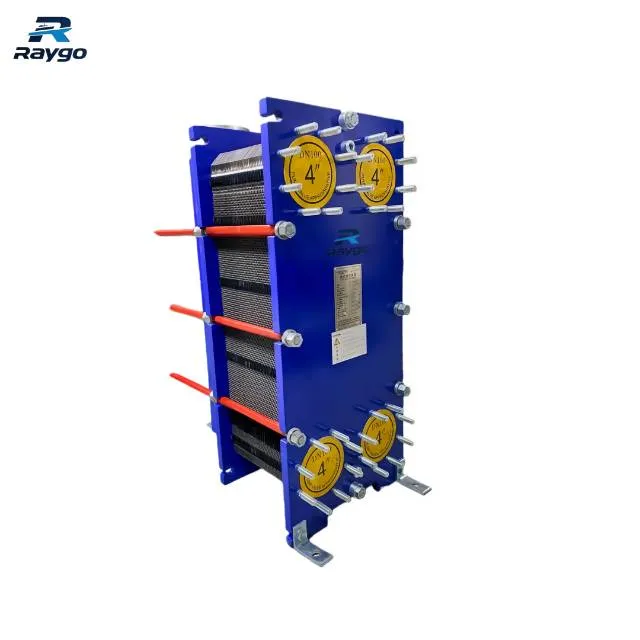
A marine plate heat exchanger uses corrugated plates to create alternating flow channels for two fluids. The fluids pass on opposite sides of the plates without mixing, while heat transfers through the plate material.
Plate designs are often considered when the engine room has limited space, the fluid is relatively clean, the project requires compact equipment, or the operator wants accessible plate inspection and gasket replacement. However, plate designs must also be checked for gasket compatibility, allowable pressure and temperature, fouling risk and tightening dimension.
Marine Shell-and-Tube Heat Exchanger
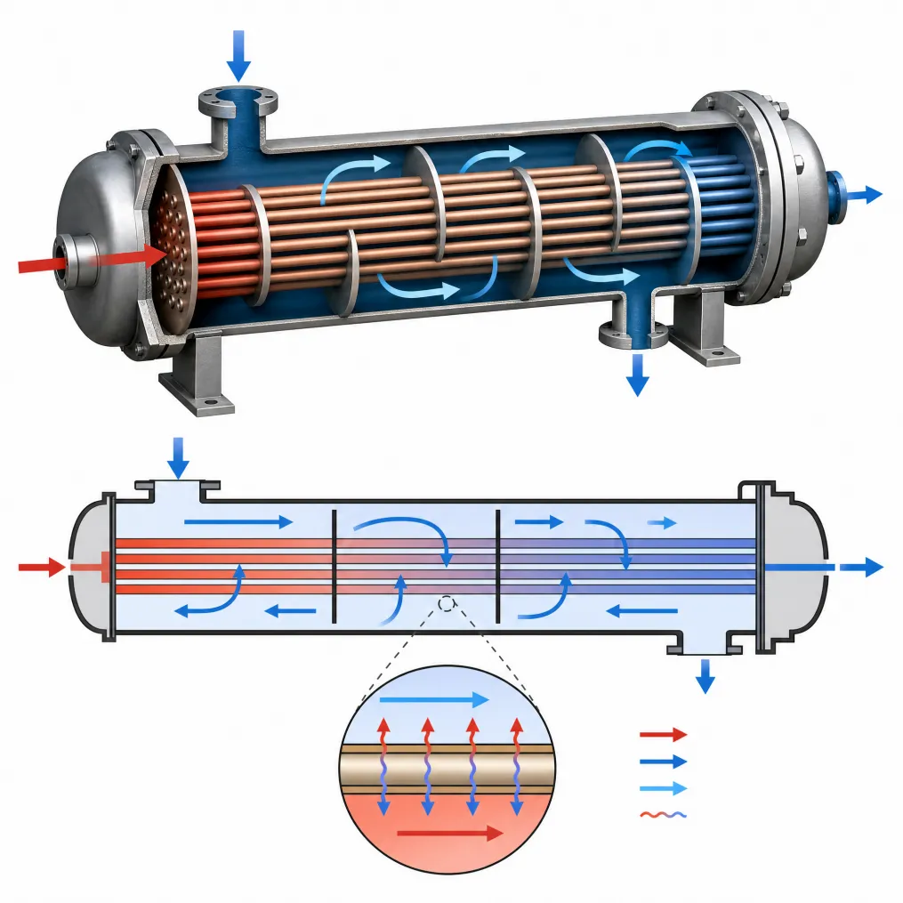
A shell-and-tube heat exchanger uses a tube bundle inside a cylindrical shell. One fluid flows through the tubes while the other fluid flows around the outside of the tubes inside the shell.
Shell-and-tube designs may be considered when the application requires a mechanically strong construction, greater tolerance to certain fouling conditions, tube-side inspection, tube plugging, retubing options, or suitability for pressure and temperature conditions outside the practical limits of a selected plate design.
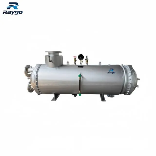
Plate vs Shell-and-Tube Marine Heat Exchangers
| Selection factor | Plate heat exchanger | Shell-and-tube heat exchanger |
| Installation footprint | Usually compact, useful where engine room space is limited. | Usually larger; requires space for shell, covers and service access. |
| Heat-transfer performance | High effective heat-transfer area in compact volume. | Depends on tube layout, baffles, flow velocity and duty. |
| Fouling tolerance | Narrow channels can be sensitive to particulate blockage and biological fouling. | Tube passages may tolerate some fouling better, depending on tube size and design. |
| Cleaning method | Plate pack can be opened for plate cleaning when space allows. | Tube side can be mechanically cleaned; shell side access depends on design. |
| Maintenance parts | Plates and gaskets are key spare parts. | Tubes, tube sheets, end cover gaskets, anodes and plugs may be involved. |
| Pressure/temperature limit | Limited by plate, gasket, frame and selected model. | Can be suitable for higher pressure or temperature duties depending on design. |
| Seawater service | Requires careful material and fouling review. | Requires tube material, tube sheet, anode and corrosion review. |
| Retrofit suitability | Good when compact footprint is needed, but connection positions must match. | Often considered when replacing existing cylindrical coolers or where existing piping fits. |
| Best fit | Compact cooling duty, accessible maintenance, relatively clean fluids and moderate design conditions. | Demanding marine service, fouling concern, pressure/temperature requirement or conventional retrofit constraints. |
| Important note: This table should not be treated as a universal ranking. Actual selection depends on heat duty, fluid properties, flow rate, pressure drop, fouling, material, installation layout and selected model. |
Step 3: Consider Seawater Conditions and Material Selection
Marine heat exchangers are different from many land-based exchangers because seawater often acts as the cooling medium. Seawater can introduce salt deposits, suspended particles, biological growth, chloride corrosion, temperature variation and different fouling patterns between operating areas.
A heat exchanger that performs well in clean freshwater may behave differently in warm coastal seawater, harbor water, shallow operating areas or routes with high biological activity.
| Material item | Selection note |
| Seawater side material | Should resist chloride corrosion and marine fouling conditions. Plate, tube and tube sheet materials must be selected according to the actual seawater duty. Raygo does not use one universal seawater alloy grade in this article because material grades are selected according to customer requirements and project conditions. |
| Freshwater/coolant side | Material should match coolant chemistry, temperature and pressure. |
| Oil side | For lube oil or hydraulic oil cooling, viscosity, temperature and cleaning method should be considered. |
| Gaskets, for plate type | Common gasket options include NBR for oil service (-15 to 120 C continuous, 130 C short-term), EPDM for water or steam (-25 to 150 C continuous, 160 C short-term), and FKM for oil or chemical service (-55 to 230 C, with 230 C short-term). Pressure capability remains model- and structure-specific. Clip-on gaskets are commonly used; replacement normally includes removing the old gasket, cleaning and drying the groove, installing the new gasket flat, engaging the clips, then reassembling and testing. |
| Tube material, for shell-and-tube type | Tube material should be confirmed for seawater, freshwater, oil or steam-related duty. Tube diameter, wall thickness and number of passes depend on the selected model and project requirement rather than one universal value. |
| Sacrificial anode | For shell-and-tube units, end-cover internal protection may use epoxy resin, anti-corrosion paint or rubber lining; stainless-steel end covers may not require coating. Sacrificial anodes are generally zinc and are commonly located in the end cover. Replacement is commonly considered when less than about 50% remains, subject to the selected design, inspection practice and project requirements. |
| Galvanic corrosion risk | Dissimilar metals and seawater can create corrosion risk if material pairing and protection are not reviewed. |
| Confirmed material boundary: shell and end cover materials are generally carbon steel or stainless steel, while exact seawater alloy grades are selected to suit the customer and project. Plate thickness, port size, plate count, tube dimensions, detailed pressure ratings, testing scope and certificate scope remain model- or project-specific and should not be presented as universal fixed values. |
Step 4: Evaluate Fouling, Cleaning and Performance Decline
Fouling is one of the most common causes of declining heat exchanger performance. Deposits on heat-transfer surfaces reduce effective heat transfer. Blocked or narrowed passages can also increase pressure drop and reduce flow.
A practical maintenance review should identify not only the symptom but also the likely cause and the first technical check.
| Warning sign | Possible cause | Technical check |
| Rising engine coolant temperature | Insufficient heat transfer, fouled surfaces, reduced seawater flow or high seawater temperature. | Compare inlet/outlet temperatures, engine load and seawater flow. |
| Increasing pressure drop | Blocked channels, scale, biological growth, debris or undersized passages. | Check pressure readings on both sides and inspect strainers or upstream filters. |
| Reduced seawater flow | Clogged strainer, pump issue, air pocket, fouled exchanger or blocked piping. | Check seawater pump, strainer, valves and pressure drop. |
| Frequent cleaning required | High fouling environment, material mismatch, poor pretreatment or too narrow flow passages. | Review operating area, water quality and selected exchanger type. |
| Visible leakage | Gasket failure, tube leakage, plate damage or cover sealing problem. | Isolate safely, inspect gaskets, plates, tubes and cover seals. |
| Fluid mixing | Plate failure, tube leak or sealing failure. | Stop operation as required and test the exchanger before return to service. |
Maintenance planning should be considered during selection, not only after performance declines. A design that is efficient when new may still be unsuitable if it is difficult to inspect, clean or remove inside the available engine room space. For CIP cleaning, chemical type, concentration, temperature and cleaning time should follow the heat exchanger manufacturer’s instructions because the correct cleaning program depends on the exchanger type, fluid and deposit. Strainer or filter fineness should likewise be selected according to exchanger type, medium and manufacturer requirements rather than a single universal marine value.
Step 5: Check Pressure Drop and Flow Balance
Heat-transfer capacity is only one part of exchanger performance. The exchanger also creates resistance to fluid flow. If pressure drop becomes too high, the cooling system may require more pumping energy or may fail to maintain the required flow rate.
A model with excellent heat transfer but excessive pressure drop may not be suitable for the complete cooling system. For both sides of the exchanger, confirm allowable pressure drop, flow rate, operating pressure and temperature. There is no single universal pressure-drop range for all Raygo heat exchangers; it is determined from exchanger type, fluid, flow rate and project design conditions, or confirmed by the heat exchanger manufacturer during selection.
When comparing models, do not compare only nominal capacity. Review heat duty, flow rates, pressure drop, operating pressure, operating temperature, connection size and maintenance access together.
Step 6: Check Installation Space, Connections and Maintenance Access
A marine engine room rarely provides unlimited space. The selected exchanger must fit the installation envelope, but physical fit is not enough. It must also be possible to clean, open, remove or service the exchanger safely.
- Overall length, width and height.
- Mounting orientation and foundation arrangement.
- Connection position and nozzle orientation.
- Pipe diameter, flange standard and bolt pattern.
- Access for plate removal, gasket replacement, cover opening or tube cleaning.
- Lifting space and removal route.
- Clearance from bulkheads, deck plates and nearby equipment.
- Drain, vent and inspection access.
For retrofit applications, the existing footprint, connection direction and maintenance route can be as important as the thermal calculation. Shell-and-tube heat exchangers are most commonly installed horizontally, while plate heat exchangers are most commonly installed vertically; final orientation must follow the selected model’s venting, draining and flow-direction requirements. For shipboard service, vibration, inclination, rolling and pitching requirements should also be reviewed and, where required, designed or tested according to the applicable classification-society rules.
Common Mistakes When Selecting a Marine Heat Exchanger
| Common mistake | Why it matters |
| Selecting only by engine power | Engine power does not fully define heat duty, flow rate or operating temperature. |
| Comparing only equipment size | A compact unit may still cause excessive pressure drop or be difficult to service. |
| Ignoring seawater quality | Warm, dirty or biologically active seawater can change fouling and material requirements. |
| Ignoring allowable pressure drop | Too much pressure drop can reduce flow and weaken the complete cooling system. |
| Using average operating conditions only | The exchanger must work at high load and design seawater temperature. |
| Treating plate and shell-and-tube as interchangeable | Each design has different cleaning methods, limits and retrofit considerations. |
| Replacing by appearance only | Photos are useful, but heat duty, flow, pressure, dimensions and connection data are still required. |
| Forgetting maintenance clearance | An exchanger may fit physically but still be impossible to clean or remove efficiently. |
Marine Heat Exchanger Selection Checklist
Before requesting a quotation or technical review, engineers and purchasing teams should collect the following data.
| Parameter | Information required |
| Engine data | Engine manufacturer, model, power, operating profile and engine maker cooling data. |
| Heat duty | Required cooling capacity or heat load. |
| Application | Jacket water, lube oil, central cooling, hydraulic oil, charge air or other duty. |
| Fluids | Primary and secondary fluid types. |
| Flow rates | Actual or required flow rate on both sides. |
| Temperatures | Inlet and outlet temperatures on both sides; design seawater temperature. |
| Pressure | Operating pressure and design pressure on both sides. |
| Pressure drop | Allowable pressure drop on both sides. |
| Configuration | Plate, shell-and-tube, or open to technical recommendation. |
| Materials | Plate, tube, shell, gasket, tube sheet, anode or coating requirements. |
| Connections | Pipe size, flange standard, nozzle direction and connection position. |
| Installation | Footprint, mounting method, space envelope and maintenance clearance. |
| Operating environment | Seawater quality, fouling risk, vessel route and ambient conditions. |
| Maintenance | Cleaning method, inspection frequency and spare parts requirement. Typical spare parts can include gaskets, plates, sealing rings, sacrificial anodes and tube plugs, depending on exchanger type. |
| Documentation | Class requirement and required project documents. Raygo can provide, as applicable, GA drawings, P&ID, thermal calculations, pressure-drop calculations, material certificates, test reports, manuals and spare-parts lists. Detailed test scope and class certificate scope remain model- and project-specific. |
Marine Heat Exchanger Replacement: What Information Should You Provide?
For replacement projects, the original model may be discontinued, the nameplate may be incomplete, or the installation space may limit the replacement design. Provide as much of the following information as possible.
- Existing heat exchanger model, manufacturer and nameplate.
- Photos of the complete unit, connections, mounting base and surrounding space.
- Drawings, if available.
- Engine model and cooling application.
- Heat-transfer capacity or original duty data.
- Fluid types, flow rates, temperatures and pressures.
- Connection dimensions, flange standard and nozzle orientation.
- Overall dimensions, footprint and mounting holes.
- Current problem, such as leakage, high temperature, high pressure drop or frequent fouling.
- Required quantity and spare parts requirement.
- Class certificate or inspection requirement.
A supplier can make a more reliable recommendation when both operating parameters and installation constraints are provided. A photo alone is rarely enough for a technically safe replacement.
Need Help Selecting a Marine Heat Exchanger?
Technical Data Required for Heat Exchanger Selection:
Marine heat exchanger selection should be based on complete operating data, not on exchanger size, price or appearance alone. Plate and shell-and-tube designs both have valid marine applications, but the correct choice depends on heat duty, fluids, pressure drop, seawater conditions, materials, installation space and maintenance access.
For a project-specific technical review, provide the engine model, heat duty, fluid types, flow rates, inlet and outlet temperatures, operating pressure, allowable pressure drop, material requirement, connection size, installation space, existing unit photos or drawings, and any class certificate requirement. Based on the confirmed company capability, Raygo can support selection recommendations, thermal calculation, structural design, class-submission support and supply coordination according to project requirements.
Related product references can be placed after the technical conclusion: Marine Plate Type Heat Exchanger, Marine Shell and Tube Heat Exchanger, and Marine Heat Exchanger category page.
Request a Marine Heat Exchanger Solution →
Contact Raygo Marine with your technical requirements for product selection and quotation.
Frequently Asked Questions
How do I choose between a plate heat exchanger and a shell-and-tube heat exchanger?
Start from the application, fluids, heat duty, pressure drop, fouling risk, material requirements, installation space and maintenance method. Plate designs are often compact, while shell-and-tube designs may be considered for demanding duty, fouling tolerance or retrofit constraints.
Is a compact heat exchanger always better for a ship engine room?
No. Compact size is useful, but the exchanger must also meet heat duty, pressure drop, material and maintenance access requirements.
What causes a marine heat exchanger to lose cooling performance?
Common causes include fouling, scale, biological growth, reduced seawater flow, blocked strainers, air pockets, incorrect flow rate, material degradation or operation beyond the design condition.
Why is pressure drop important?
Excessive pressure drop can reduce the required flow rate and affect cooling system performance, even if the exchanger has sufficient nominal heat-transfer capacity.
What information is needed to size a marine heat exchanger?
Key data includes heat duty, fluid types, flow rates, inlet and outlet temperatures, operating pressure, allowable pressure drop, material requirement and installation space.
Can an old marine heat exchanger be replaced without the original model?
It may be possible, but the supplier needs operating data, dimensions, connection details, photos, drawings and the cooling application to evaluate an alternative.
What should be checked for seawater cooling service?
Check seawater temperature, fouling risk, chloride corrosion risk, suspended particles, material selection, anode arrangement if applicable, and cleaning access.
Should the article link to plate and shell-and-tube product pages?
Yes, but links should appear as related product references after the technical explanation, not as repeated sales messages in the main technical sections.