Why Shell-and-Tube Heat Exchangers Still Matter at Sea
A bundle of tubes sits inside a cylindrical shell; one fluid runs through the tubes, and the other runs around them, and heat crosses the tube walls between the two. This simple arrangement remains valuable on ships because it can be engineered for high pressure, high temperature, condensing steam, aggressive seawater and fluids that may foul or attack gasket materials.
Compared with compact plate designs, a shell-and-tube exchanger is usually heavier and less space-efficient. Its strengths are mechanical robustness, flexible material selection, inspectable tubes, and the ability to isolate, clean, plug or replace individual tubes or the complete bundle.
| Important: A heat exchanger is pressure equipment. The final design, repair method and test pressure must follow the manufacturer’s instructions, the vessel’s class rules, approved drawings and the applicable code—not a general blog article. |
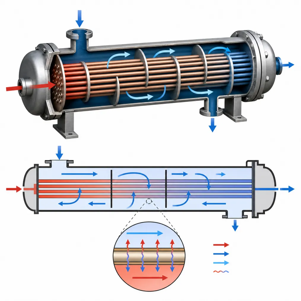
Basic shell-and-tube arrangement: two separate fluid circuits exchange heat across the tube wall.
How a Shell-and-Tube Heat Exchanger Works
The tube-side fluid enters through a channel or water box, passes through the tube bundle, and leaves at the opposite end. In a two-pass or multi-pass design, partition plates redirect the fluid through the bundle more than once to increase velocity and improve heat transfer within the allowable pressure drop.
Baffles create repeated cross-flow zones and changes in direction on the shell side. In practice, the overall shell-side pattern combines cross-flow with leakage and bypass streams.
Baffles perform two jobs: they direct shell-side flow across the tubes and support the tubes against sagging and vibration. Tube sheets anchor the tubes and maintain separation between the two fluids. If a tube or tube-to-tubesheet joint leaks, the two circuits may contaminate each other even though they are separated during normal operation.
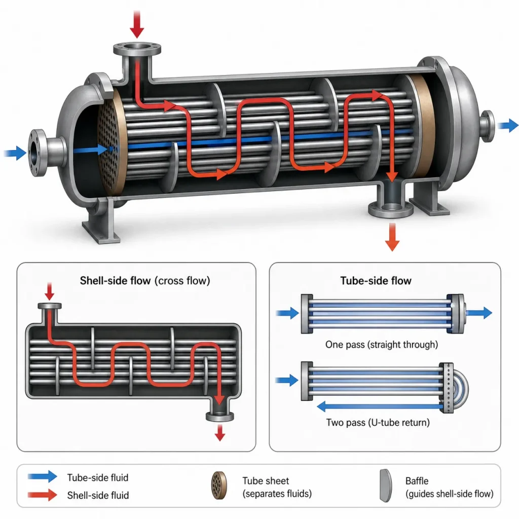
Shell-side baffled flow and one-pass/two-pass tube-side arrangements
Heat-transfer duty in plain language
The exchanger must transfer a specified heat duty. On either side, the duty is related to fluid flow rate, heat capacity and temperature change. Designers then size enough surface area so that the available temperature difference can drive that duty after allowing for wall resistance and expected fouling.
| Design term | What it means in practice | Why operators should care |
| Heat duty | The amount of heat that must be added or removed. | Determines required surface area and utility demand. |
| Overall heat-transfer coefficient (U) | A combined measure of convection, tube-wall conduction and fouling resistance. | A falling effective U often indicates fouling or flow deterioration. |
| Temperature driving force | The average useful temperature difference between the hot and cold streams. | A small approach temperature generally requires more area. |
| Allowable pressure drop | The pressure loss that pumps or the process can tolerate. | Higher velocity can improve heat transfer but also raises pressure drop and erosion risk. |
Main Components and Common Construction Types
| Component | Function | Marine design/maintenance note |
| Shell | Pressure vessel containing the shell-side fluid. | Check corrosion allowance, supports, drains, vents and external coating. |
| Tube bundle | Provides the heat-transfer surface; may use straight, U-shaped or enhanced tubes. | Tube material, wall thickness and cleanability must match the duty. |
| Tube sheets | Anchor and seal the tubes at the ends of the bundle. | Material compatibility with tubes and water boxes is critical for galvanic control. |
| Baffles/support plates | Guide shell-side flow and support tubes. | Poor baffle design or excessive cross-flow velocity can contribute to vibration and fretting. |
| Channel/water box and covers | Distribute tube-side flow and provide access. | Allow room for opening covers, removing gaskets and cleaning tubes. |
| Expansion joint or floating head | Accommodates differential thermal expansion where required. | Selection affects inspectability, cost and leakage risk. |
| Gaskets and bolting | Seal removable covers and flanged joints. | Material and tightening procedure must suit pressure, temperature and fluid chemistry. |
Common exchanger configurations
| Configuration | Advantages | Limitations / best-fit use |
| Fixed tube sheet | Simple, compact and economical. | Shell side is difficult to mechanically clean; thermal expansion must be checked. |
| U-tube | Handles differential thermal expansion without a shell expansion joint. | Tube bends are harder to inspect and mechanically clean; inner tubes cannot always be replaced individually. |
| Floating head / removable bundle | Both sides can be inspected and the bundle can be removed. | More complex, heavier and typically more expensive; needs pull space. |
| One-pass or multi-pass | Pass arrangement adjusts velocity and thermal performance. | More passes increase pressure drop and can complicate distribution. |
Typical Marine Applications
Shell-and-tube units are used wherever a ship needs reliable cooling, heating, evaporation or condensation. The exact circuit arrangement varies by vessel type and machinery package.
- Main and auxiliary engine jacket-water coolers and central freshwater coolers.
- Lubricating-oil, hydraulic-oil and gearbox-oil coolers.
- Steam condensers, drain coolers, feed-water heaters and fuel-oil heaters.
- Charge-air coolers, refrigeration condensers/evaporators and HVAC duties.
- Cargo heating/cooling, tank-cleaning systems and process duties on specialized vessels.
- Waste-heat recovery and auxiliary thermal systems, subject to temperature, pressure and class requirements.
When Shell-and-Tube Is Preferred Over Plate Designs
Shell-and-tube units are often preferred where steam, high pressure, high temperature, severe fouling or gasket compatibility is a concern. However, “shell-and-tube” is not automatically the safer or better choice; welded plate, semi-welded plate and fully welded compact exchangers may also be suitable. Selection should compare the actual design pressure, temperature, fluid hazard, fouling behavior, maintenance strategy and available space.
| Decision factor | Shell-and-tube | Plate-type exchanger |
| Footprint and weight | Usually larger and heavier. | Usually more compact for the same duty. |
| High pressure / high temperature | Broad design flexibility; robust welded or expanded tube joints. | Depends strongly on plate construction, gasket material and model rating. |
| Mechanical cleaning | Straight tubes can be brushed or hydro-jetted; removable bundles offer shell-side access. | Opening gives direct plate access, but gasket handling and correct reassembly are important. |
| Fouling tolerance | Can be designed with larger passages and removable/cleanable tubes. | High turbulence may reduce fouling, but narrow channels can plug with large debris. |
| Thermal efficiency | Typically lower heat-transfer coefficient and larger approach temperature. | Often higher heat-transfer coefficient and closer temperature approach. |
| Leak failure mode | Tube failure can mix fluids; individual tubes may be isolated. | Plate or gasket failure can mix fluids or leak externally, depending on design. |
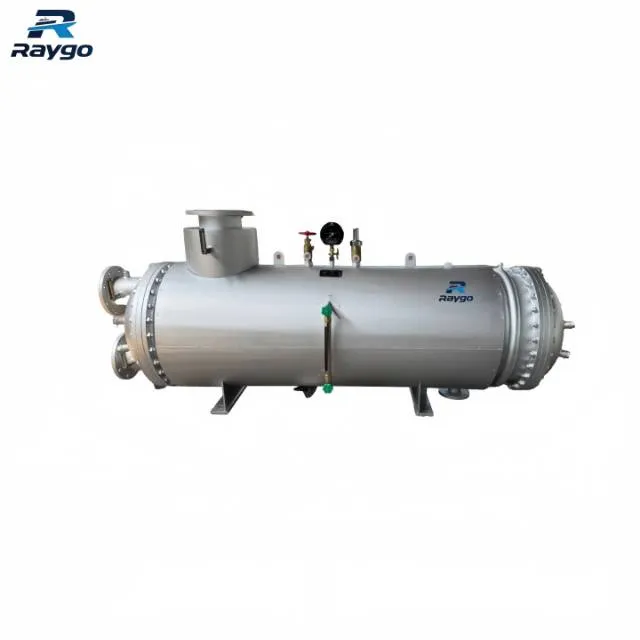
Example marine shell-and-tube heat exchanger. Final nozzle orientation and support arrangement are project-specific
Thermal and Hydraulic Design: What Must Be Specified
A reliable quotation starts with process data, not only connection size or shell diameter. Supplying incomplete data can produce a unit that fits the pipework but misses the heat duty—or meets the duty while creating excessive pump load.
| Required input | Examples | Design consequence |
| Fluid identity and composition | Seawater, freshwater, lube oil, fuel oil, steam/condensate, glycol or refrigerant. | Controls corrosion, viscosity, fouling, material and sealing choices. |
| Flow rate | Normal, minimum and maximum operating flow. | Sets velocity, heat-transfer coefficient and pressure drop. |
| Inlet/outlet temperatures | Normal and worst-case seasonal conditions. | Defines heat duty and temperature driving force. |
| Design/operating pressure and temperature | Both shell side and tube side. | Controls mechanical design, code/class scope and material strength. |
| Allowable pressure drop | Available pump head on each side. | Limits passes, nozzle size and acceptable velocity. |
| Water chemistry and route | Salinity, chlorides, sulfides, sediment, biological activity and periods of stagnation. | Critical for tube alloy, coatings, anodes and cleaning plan. |
| Fouling allowance | Based on service history and cleaning frequency. | Too little margin shortens run time; excessive margin can lower velocity and worsen deposition. |
| Installation envelope | Footprint, lifting route, cover-opening space, bundle pull length and nearby equipment. | Determines maintainability, not just fit at delivery. |
Velocity is a trade-off—not a single “correct number”
Low velocity can encourage sedimentation, biofouling and poor heat transfer. Excessive velocity can increase pressure drop, impingement attack, erosion-corrosion and tube vibration. Acceptable velocity depends on the alloy, tube diameter, suspended solids, inlet geometry, temperature and manufacturer guidance. Avoid publishing one universal velocity limit for all seawater exchangers.
Tube Materials and Seawater Corrosion
Material selection must consider the complete wetted system: tubes, tube sheets, water boxes, coatings, fasteners, anodes and connected piping. Selecting a highly corrosion-resistant tube does not automatically prevent failure if the surrounding metals form an unfavorable galvanic couple or if stagnant deposits create localized attack.
| Material / alloy family | Typical marine use | Strengths | Important cautions | |
| 90/10 Cu-Ni (e.g., C70600) | Common seawater coolers and condensers. | Good seawater resistance; protective surface film; useful resistance to biofouling. | Sensitive to polluted/sulfide-bearing water, deposits, poor commissioning and excessive impingement. | |
| 70/30 Cu-Ni (e.g., C71500) | More demanding seawater service. | Generally higher strength and resistance to high-velocity seawater than 90/10 Cu-Ni. | Cost and galvanic compatibility still require evaluation. | |
| Commercially pure titanium (often Grade 2) | Aggressive or high-chloride seawater; long-life coolers/condensers. | Excellent resistance to general seawater corrosion and chlorides. | Higher initial cost; galvanic effects on less-noble water boxes/tube sheets and hydrogen uptake conditions must be assessed. | |
| Austenitic stainless steel | Freshwater, lube oil and selected clean services. | Good general corrosion resistance and fabrication availability. | Chloride pitting and crevice corrosion can occur, especially in warm, stagnant or deposit-covered seawater. | |
| Duplex / super duplex stainless steel | Selected high-chloride services where qualified by design. | Higher chloride resistance and strength than common austenitic grades. | Grade, welding quality, temperature and crevice geometry are decisive; not a universal substitute for titanium. | |
| Carbon steel | Shells, channels or non-seawater sides in many duties. | Economical and readily fabricated. | Needs corrosion allowance, coating, lining or cathodic protection when exposed to seawater. | |
| Material note: “Stainless steel” is not a single seawater-performance category. Resistance to chloride pitting, crevice corrosion and stress-corrosion cracking varies greatly among 304/316, duplex, super-duplex and higher-alloy grades. The exact grade, fabrication condition, water chemistry, temperature and stagnation risk must all be specified. | ||||
Galvanic compatibility and sacrificial anodes
Zinc or aluminum anodes may be fitted in water boxes to protect nearby susceptible components. The anode must have electrical continuity to the protected metal and must be placed where water reaches it. Anodes are consumable parts: inspect dimensions and attachment condition at every scheduled opening and replace them before they are exhausted.
Anodes are not a cure for poor material pairing, damaged coating or uncontrolled stray current. Tube-sheet and water-box materials should be selected as a system, and the effect of coupling titanium or stainless tubes to copper-alloy or carbon-steel components should be reviewed by the designer.
Common Damage Mechanisms
| Damage mechanism | What causes it | Typical evidence |
| Scaling and crystallization | Hardness salts or process components precipitate on hot surfaces. | Hard deposits, rising approach temperature, higher pressure drop. |
| Marine biofouling | Organisms attach and grow during seawater operation or stagnation. | Slime, shells, blocked tubes, reduced flow and heat transfer. |
| Sediment / particulate fouling | Sand, rust, silt and debris settle or lodge in tubes and at baffles. | Uneven plugging, inlet-end wear, high pressure drop. |
| Pitting and crevice corrosion | Chlorides, deposits, tight crevices, high temperature or stagnant water. | Deep localized pits, attack under gaskets/deposits, sudden pinhole leaks. |
| Erosion-corrosion / impingement | High velocity, poor inlet distribution, entrained solids or two-phase flow. | Thinning near tube inlets, directional grooves, horseshoe-shaped attack. |
| Galvanic corrosion | Dissimilar metals electrically connected in seawater. | Accelerated attack of the less-noble component near the joint. |
| Vibration and fretting | Flow-induced vibration, unsupported spans or loose baffles. | Polished wear marks, tube thinning at support plates, noise or repeated leaks. |
| Thermal fatigue / expansion stress | Frequent temperature cycling or restrained differential expansion. | Cracks, tube-to-tubesheet leakage or shell/nozzle distress. |
Fouling, Scaling and Pressure Drop: What to Monitor
The first signs of tube-side fouling are often reduced heat transfer and a higher process outlet temperature. However, temperature alone is not enough: compare temperatures with flow rate, load, seawater inlet temperature and valve position. A warmer sea or lower flow can mimic fouling.
Trend the same measurements at consistent operating conditions. Useful indicators include inlet and outlet temperatures on both sides, differential pressure across each side, flow rate, pump condition, bypass-valve position, fluid levels and evidence of cross-contamination.
| Observed symptom | Possible causes | Immediate checks |
| Heat duty falls; pressure drop rises | Fouling, blocked tubes, closed valve, reduced pump performance. | Verify flow and valve lineup; compare differential pressure with clean baseline. |
| Heat duty falls; pressure drop unchanged or lower | Low flow, bypass leakage, air/gas pocket, poor temperature driving force. | Check pumps, vents, bypasses, temperature sensors and process load. |
| Unexpected fluid contamination | Leaking tube, tube-to-tubesheet joint or cracked partition plate. | Sample both fluids, isolate if required, pressure-test or leak-test under approved procedure. |
| Repeated inlet-end tube failures | Impingement, debris, excessive velocity, poor water-box distribution. | Inspect inlet geometry, strainers, tube-end condition and operating flow. |
| Rapid anode consumption | Large exposed cathodic area, coating damage, stray current or incorrect anode selection. | Check electrical continuity, coating, nearby metals and system grounding. |
Inspection, Cleaning and Maintenance
Safe preparation before opening
1. Stop the unit, isolate both fluid circuits, lock out energy sources and confirm zero pressure.
2. Drain, cool and vent the equipment. Where hazardous fluids may be present, carry out gas testing and cleaning in accordance with the vessel’s permit-to-work system.
3. Record “as-found” temperatures, pressure drops, flow rates, leak history and anode condition before cleaning.
4. Mark cover orientation, partition arrangement and gasket position to support correct reassembly.
Cleaning methods
| Method | Suitable for | Key precautions |
| Mechanical brushing / rodding | Loose deposits in straight tubes. | Use tools softer than the tube material; avoid scoring thin-wall tubes. |
| Water jetting | Sludge, marine growth and many tenacious deposits. | Control pressure, nozzle type and tube support; protect personnel and prevent tube-end damage. |
| Chemical cleaning | Scale or deposits that dissolve in a compatible chemical. | Confirm compatibility with tubes, tube sheets, coatings and gaskets; neutralize, flush and dispose responsibly. |
| Backflushing / online cleaning | Selected systems designed for it. | Effectiveness depends on deposit type and installed valves/cleaning equipment. |
Inspection methods
- Visual inspection of water boxes, tube sheets, coatings, gaskets, partition plates and tube inlets.
- Borescope inspection where tube geometry allows.
- Tube-wall examination by an appropriate NDT method—such as eddy-current testing for many non-ferromagnetic tubes or other specialist methods for ferromagnetic materials.
- Dye-penetrant examination of accessible non-porous surfaces and suspect tube-to-tubesheet areas, where approved.
- Dimensional checks of sacrificial anodes, tube-end thinning and gasket seating surfaces.
- Pressure or leak testing after repair, using the approved test medium, pressure, hold time and safety procedure.
After repair, carry out an approved hydrostatic or leak test using the specified test medium, pressure, hold time and safety controls. Hydrostatic testing is generally preferred because compressed gas stores substantially more energy; pneumatic testing should only be used when specifically justified and controlled.
Tube leakage and plugging
A leaking tube may be plugged at both ends to isolate it, provided the plug material and installation method are approved for the tube and tube sheet. Plugging reduces effective heat-transfer area and can alter local flow distribution.
The acceptable number of plugged tubes depends on the exchanger design, remaining thermal margin, flow redistribution, vibration risk, OEM guidance and class requirements. When plugging begins to compromise duty or reliability, bundle repair or replacement should be evaluated.
Practical maintenance intervals
| Interval | Recommended checks | Trigger for earlier action |
| Each watch / routine rounds | Leaks, vibration/noise, inlet/outlet temperatures, pressure indications and abnormal valve positions. | Sudden temperature shift, contamination, pressure instability or visible leakage. |
| Weekly or monthly trending | Normalized temperature approach, differential pressure, flow rate and pump/strainer condition. | Progressive deviation from the clean baseline. |
| Planned opening / dry dock | Tube cleanliness, NDT as required, anodes, coatings, gaskets, bolting, water-box condition and documentation. | Operating history, class survey scope, water quality or repeated failures. |
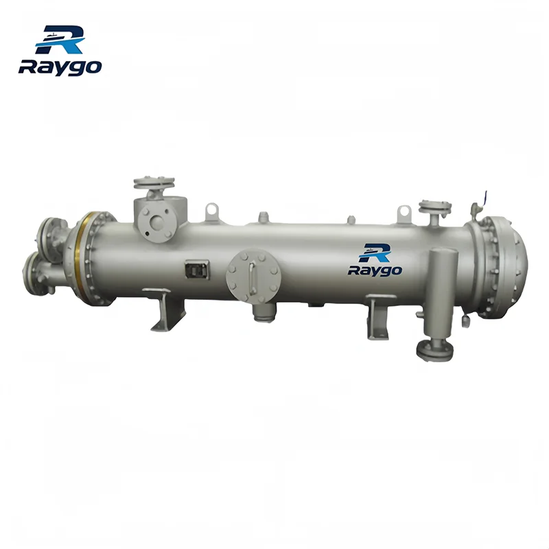
Example marine heat exchanger. Access covers, vents, drains and lifting points should be verified against the maintenance plan
New Build vs. Retrofit Selection Data
| Project type | Information required | Why it matters |
| Newbuild | Full process datasheet; design/operating conditions; heat duty; pressure drop; materials; code/class; nozzle loads; foundation and lifting plan. | Defines thermal performance, mechanical integrity and approval basis. |
| Retrofit | All newbuild data plus existing nozzle locations, flange standards, installed envelope, foundation bolts, lifting route, bundle pull space, dry weight/wet weight and center of gravity. | A thermally correct unit can still fail as a retrofit if it does not fit, connect or remain maintainable. |
| Both | Confirm normal, minimum and maximum conditions; seasonal seawater temperature; corrosion/fouling history; spare parts and documentation scope. | Prevents under-sizing, excessive pressure drop and avoidable lifecycle cost. |
Documentation and Classification Requirements
Classification-society involvement depends on the exchanger’s service, pressure, temperature, fluid hazard, vessel class and flag. Confirm the approval route before purchase. A supplier’s general certificate or a previous approval for another vessel may not satisfy the current project.
| Document / activity | Typical content | Good practice |
| Approved drawings and datasheet | General arrangement, nozzles, supports, materials, design conditions and heat-transfer duty. | Freeze revision status before fabrication and retain the final “as built” set. |
| Design calculations | Thermal rating, pressure-drop calculation and mechanical/code calculations. | State assumptions, fouling factors and corrosion allowances clearly. |
| Material traceability | Material certificates for pressure parts, tubes, tube sheets and critical fasteners. | Match certificates to heat/lot numbers and the bill of materials. |
| Fabrication quality records | Welding procedures/qualifications, welder qualifications, tube-expansion or tube-welding procedure, NDT reports and dimensional checks. | Agree inspection hold points before production. |
| Pressure/leak test records | Test medium, pressure, duration, temperature, acceptance and witness details. | Use approved procedures and calibrated instruments. |
| Operation and maintenance manual | Installation, tightening, start-up, shutdown, cleaning, spare parts and repair limits. | Keep a controlled copy in the ship’s technical file. |
| Class certificates / survey records | Documentation required by ABS, BV, CCS, DNV, LR, KR, RINA, ClassNK or other applicable society. | Requirements vary; confirm the society and notation for the actual vessel. |
Commissioning and Shutdown Practices That Extend Service Life
- Flush construction debris and verify strainers before introducing seawater.
- Vent trapped air; gas pockets reduce heat transfer and may accelerate localized corrosion.
- Bring flow and temperature on gradually where thermal shock or differential expansion is a concern.
- For copper-nickel tubes, follow the supplier’s commissioning guidance so a protective surface film can develop under suitable water conditions.
- Avoid leaving dirty seawater stagnant in the exchanger for extended periods. Drain, flush or preserve the unit according to the approved shutdown procedure.
- After cleaning, restore anodes, gaskets, partition plates and cover-bolt tightening in the correct sequence; then verify leak-tightness and baseline performance.
Frequently Asked Questions
Can a shell-and-tube exchanger use seawater on either side?
Yes, but seawater is commonly placed on the tube side because straight tubes are easier to inspect and mechanically clean, and a leaking tube can often be isolated. The final arrangement depends on pressure, corrosion, fouling, cleanability and contamination risk.
Does higher seawater velocity always reduce fouling?
No. Moderate velocity can reduce settlement and improve heat transfer, but excessive velocity may cause erosion-corrosion, impingement and vibration. The design window is material- and geometry-specific.
Is titanium always the best seawater tube material?
Titanium offers excellent seawater corrosion resistance, but lifecycle choice also depends on cost, galvanic compatibility, fabrication, thermal design, water-box materials, operating conditions and repair capability. “Most corrosion resistant” is not automatically “best overall.”
When should a tube bundle be replaced instead of cleaned or plugged?
Replacement becomes more attractive when failures are widespread, tube-wall loss is systemic, plugging has consumed thermal margin, support damage causes repeated fretting, or repair cannot meet class/OEM requirements. Use inspection data and a thermal/mechanical reassessment rather than tube count alone.
Buyer and Operator Checklist
| Before ordering | Before commissioning | During operation / maintenance |
| Confirm heat duty, fluids, all temperature/pressure cases and allowable pressure drops. | Verify flushing, venting, valves, strainers and instrumentation. | Trend temperatures, differential pressure and flow against a clean baseline. |
| Specify materials as a complete galvanic system—not tubes alone. | Check anodes, coatings, gaskets, bolting and correct pass partitions. | Investigate contamination or sudden performance changes promptly. |
| Confirm code, class, certification, inspection and document requirements. | Record initial performance data at stable load. | Clean with methods compatible with tube and coating materials. |
| Check footprint, lifting route, cover access and bundle pull space. | Store approved drawings, certificates and O&M instructions onboard. | Reassess performance after repeated plugging or major repair. |
Technical Review Data to Share with the Supplier
For an accurate selection or retrofit review, provide the heat duty, fluid composition, normal/minimum/maximum flow rates, inlet and outlet temperatures, operating and design pressures, allowable pressure drop, preferred materials, fouling history, connection standards and sizes, class society, documentation scope, installation envelope, maintenance access and photographs/drawings of the existing arrangement.
A matched recommendation should state the thermal rating, pressure drop, materials, tube arrangement, corrosion-control features, overall dimensions, operating weight, maintenance clearances, applicable design standard and required certification.
Request a Marine Shell-and-Tube Heat Exchangers quotation from Raygo Marine.